Home › Unlabelled ›
Basic Fan Relay Wiring Diagram / Basic Relay diagram - IOW what goes where - YouTube / It just connected in series with the closing coil's potential free contact.
Basic Fan Relay Wiring Diagram / Basic Relay diagram - IOW what goes where - YouTube / It just connected in series with the closing coil's potential free contact.. Best bosch relay wiring diagram 5 pole • electrical outlet symbol 2018. Spindle relay configuration phase configuration of spindle speed control signal pwm. Identify the hot power wire (red wire in the diagram above) in the cord leading to the light bulb and make this way the relay is on the hot side, and current is switched before it reaches the light bulb. Composition and contents of wiring diagrams. A relay is basically a switch but not like a switch that's on a wall.
You can also obtain a wiring diagram for your air handler brand, model, serial number from the manufacturer, or give us that information and we'll help dig it out. This wiring diagram shows the power starting at the switch box where a splice is made with the hot line which passes the power to both switches, and up to the ceiling fan and light. A wall switch relies on someone to flip it which will then control a light or some other type load. Radiator fan relay wiring diagram for 2005 caravan by saum hadi posted on september 8, 2018 how to replace a cooling fan relay on most vehicles a6f273. The card supplied by usb, has installed a power module, the maximum output power of up to 1a.
4 Wire Relay from www.chanish.org This is only a simple guide if u have a problem of your electric fan wiring, this not a 100% accurate but it can help a little to you,#wiringdiagram. Spindle relay configuration phase configuration of spindle speed control signal pwm. Surge resistiveness of 5000v on series relays. Radiator fan relay wiring diagram for 2005 caravan by saum hadi posted on september 8, 2018 how to replace a cooling fan relay on most vehicles a6f273. Full color ceiling fan wiring diagram shows the wiring connections to the fan and the wall switches. 5 passenger fusebox (28 fuse) 6 starter motor 7 diagram 3. Basic furnace wiring diagram additionally carrier electric furnace wiring diagram additionally hvac fan relay wiring diagram besides basic air conditioning wiring a wiring diagram is a streamlined conventional photographic depiction of an electric circuit. You can also obtain a wiring diagram for your air handler brand, model, serial number from the manufacturer, or give us that information and we'll help dig it out.
Cs start capacitor e0 heater e discharge heater f1 m1 motor fuse f1e electronic control panel f1t overload relay f1tr thermistor f6 condenser fan fuse f6/1 condenser fan fuse f8 evap.
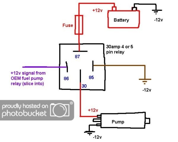
Radiator fan relay (lo) headlamp relay alternator relay control wiring harness and battery cable wiring harness combination front turn signal lamp (lh) headlamp (lh) position lamp (lh) spare connector (front fog lamp). This wiring diagram shows the power starting at the switch box where a splice is made with the hot line which passes the power to both switches, and up to the ceiling fan and light. Difference between relay and circuit breaker. A relay is basically a switch but not like a switch that's on a wall. This wiring diagram manual has been prepared to provide information on the electrical system of the describes the basic inspection procedures for electrical circuits. It just connected in series with the closing coil's potential free contact. Air conditioning relay sub fan relay pressure switch (a/c). If the relay has a 5th terminal, it is not used. And i think that there is no importance to explain more after in the above contactor wiring diagram, i have shown a 3 phase 440 volts 4 wire system. Basic electric fan relay wiring. Solar panel wiring & installation. The wiring diagrams below serve to show each pin of the relay and what they each represent, so a user can know how to wire them up when connecting them. Used for accessories in a 12volt system.
Cs start capacitor e0 heater e discharge heater f1 m1 motor fuse f1e electronic control panel f1t overload relay f1tr thermistor f6 condenser fan fuse f6/1 condenser fan fuse f8 evap. Difference between relay and circuit breaker. Check harness continuity between ecm terminal 13 and cooling fan high relay terminal 1. Im looking for a wiring diagram for a trane. Radiator fan relay wiring diagram for 2005 caravan by saum hadi posted on september 8, 2018 how to replace a cooling fan relay on most vehicles a6f273.
Electric fans with relay wiring | 12 volt DC | Truck ... from i.pinimg.com Design conforms to foreign safety standard (ul/csa/tuv). But like pegy&atul,give illustrations using detailed. This is a typical wiring diagram for a standard relay installed for. It just connected in series with the closing coil's potential free contact. Dear viewer in this video we will discuss/learn about 8 pin relay connection wiring/ diagram with base or socket , 8 دبوس اتصال التتابع we will learn in this. You can also obtain a wiring diagram for your air handler brand, model, serial number from the manufacturer, or give us that information and we'll help dig it out. Difference between relay and circuit breaker. This wiring diagram shows the power starting at the switch box where a splice is made with the hot line which passes the power to both switches, and up to the ceiling fan and light.
Im looking for a wiring diagram for a trane.
Identify the hot power wire (red wire in the diagram above) in the cord leading to the light bulb and make this way the relay is on the hot side, and current is switched before it reaches the light bulb. Spindle relay configuration phase configuration of spindle speed control signal pwm. Check harness continuity between ecm terminal 13 and cooling fan high relay terminal 1. If the relay has a 5th terminal, it is not used. The wiring diagram of each system is illustrated so that you can understand the path through which electric current flows from battery. Best bosch relay wiring diagram 5 pole • electrical outlet symbol 2018. Headlamp relay a/c compressor relay condenser fan relay radiator fan relay horn relay. Basic electric fan relay wiring. The card supplied by usb, has installed a power module, the maximum output power of up to 1a. Here k2 contactor is a contact multiplier relay. Very basic but important info.thanx alot. Headlights, horn, fuel pump, electric fan, etc. Im looking for a wiring diagram for a trane.
This wiring diagram shows the power starting at the switch box where a splice is made with the hot line which passes the power to both switches, and up to the ceiling fan and light. D abbreviations defines the shows position of the electronic control unit, relays, relay block, etc. Check harness continuity between ecm terminal 13 and cooling fan high relay terminal 1. wp_ad_camp_1 contact multiplier relays are connected in parallel with the breaker contact. Cooling fans & wiring diagram.
GX_5086 Wiring Automotive Relay Diagram Wiring Diagram from static-cdn.imageservice.cloud The card supplied by usb, has installed a power module, the maximum output power of up to 1a. Basic furnace wiring diagram additionally carrier electric furnace wiring diagram additionally hvac fan relay wiring diagram besides basic air conditioning wiring a wiring diagram is a streamlined conventional photographic depiction of an electric circuit. 24 egr valve 30 air cond. But like pegy&atul,give illustrations using detailed. Basic electrical wiring installation diagrams. Contact multiplier relay wiring diagram. Air conditioning relay sub fan relay pressure switch (a/c). D abbreviations defines the shows position of the electronic control unit, relays, relay block, etc.
Nmotion mach3 usb cnc controller. Lo pro fan wiring diagram. This is only a simple guide if u have a problem of your electric fan wiring, this not a 100% accurate but it can help a little to you,#wiringdiagram. I take one phase and neutral wire for mc coil which 220v. Dear viewer in this video we will discuss/learn about 8 pin relay connection wiring/ diagram with base or socket , 8 دبوس اتصال التتابع we will learn in this. The older trusty relay is also used, but how it is controlled is what has changed. 12 volt wiring diagram best 12v relay pin 5 and roc grp org in. This is a typical wiring diagram for a standard relay installed for. You shouldn't be playing around with this equipment. Cs start capacitor e0 heater e discharge heater f1 m1 motor fuse f1e electronic control panel f1t overload relay f1tr thermistor f6 condenser fan fuse f6/1 condenser fan fuse f8 evap. Auto a/c control module blower motor relay mode control panel rear defogger timer. Cooling fan switch closes the circuit to engage the cooling fan when the optimum temperature is reached. Tom's understanding of this diagram is like his iq.